
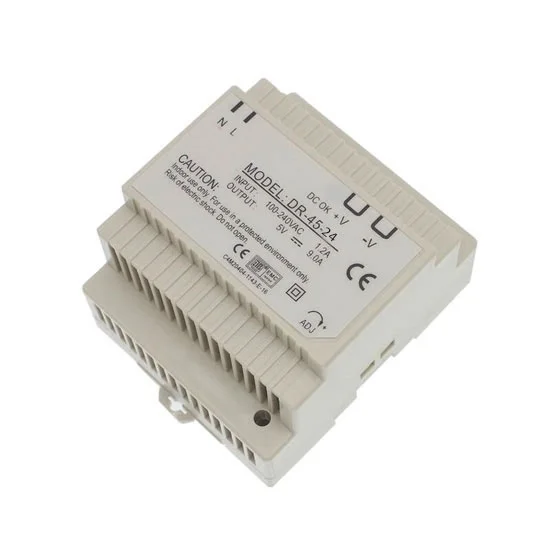
Description
Features
- Universal AC input/Full range
- Protections: short circuit, overload, overvoltage and over temperature
- Cooling by free air convection
- Installed on DIN rail TS-35/7.5 or 15
- LED indicator for power on
- 100% full load burn-in test
Specification
| Model | ATO-DR-45-24 | |
| Output |
DC Voltage | 24V |
| Rated Current | 2A | |
| Current Range | 0 ~ 2A | |
| Rated Power | 48W | |
| Ripple & Noise (Max.)(Note 2) | 480mVp-p | |
| Voltage Adjust Range | 21.6 ~ 26.4V | |
| Voltage Tolerance (Note 3) | ±1.0% | |
| Line Regulation | ±1.0% | |
| Load Regulation | ±1.0% | |
| Setup, Rise, Holdup Time | 800ms, 60ms, 60ms/230V AC | |
| Input | Voltage Range | 85 ~ 264V AC or 120 ~ 370V DC |
| Frequency Range | 47~63Hz | |
| Efficiency (Typ.) | 80% | |
| AC Current (Typ.) | 1.5A/115V AC 0.75A/230V AC | |
| Inrush Current (Typ.) | Cold start: 28A/115V AC 56A/230V AC | |
| Leakage Current | <1mA/240V AC | |
| Protection | Overload | 105~150% rated output power Protection type: Constant current limiting, recovers automatically after fault condition is removed. |
| Overvoltage | 27.6V ~ 32.4V Protection type: Shut off o/p voltage, clamping by zener diode. |
|
| Over temperature | Tj 135℃ typically (U1) detect on heat sink of power transistor Protection type: Shut down output voltage, re-power on to recover. |
|
| Environment | Working Temperature | -20 ~ +50℃ |
| Working Humidity | 20~90% RH non-condensing | |
| Storage Temperature | -20~+85℃ | |
| Storage Humidity | 10~95% RH non-condensing | |
| Temperature Coefficient | ±0.03%/℃ (0~50℃) | |
| Vibration | 10 ~ 500Hz, 2G 10min./1 cycle, period for 60min. each along X, Y, Z axes | |
| Safety & EMC (Note 4) | Safety Standards | UL60950-1, TUV EN60950-1 Approved |
| Withstand Voltage | I/P-O/P:3KVAC I/P-FG:2.0KVAC O/P-FG:0.5KVAC | |
| Isolation Resistance | I/P-O/P, I/P-FG, O/P-FG: 100M Ohms/500VDC/25℃/70% RH | |
| EMC Emission | Compliance to EN55022 (CISPR22) Class B, EN61000-3-2, -3 | |
| EMC Immunity | Compliance to EN61000-4-2, 3, 4, 5, 6, 8, 11, EN55024, EN61000-6-2, EN61204-3, heavy industry level, criteria A | |
| Others | MTBF | ≥364.6K hrs MIN. MIL-HDBK-217F (25℃) |
| Dimension | 93*78*56mm (L*W*H) | |
| Weight | 0.31kg | |
| Note | 1. All parameters NOT specially mentioned are measured at 230V AC input, rated load and 25°C of ambient temperature. 2. Ripple & noise are measured at 20MHz of bandwidth by using a 12″ twisted pair-wire terminated with a 0.1uf & 47uf parallel capacitor. 3. Tolerance includes set up tolerance, line regulation and load regulation. 4. The switching power supply is considered a component which will be installed into final equipment. Please make sure that the final equipment still meets EMC directives. |
Dimensions (Unit: mm)
Details
Tips: User guide of switching power supply (SMPS)
- Output calculation
Switching power supply works at an efficiency of over 80%. When making a selection of output current, users shall measure and calculate maximum sock current of electric equipment to ensure higher cost-performance ratio of selected switching power supply. - Ground connection
In comparison with linear power supply, switching power supply generates more noise. Electric devices which are sensitive to common mode noise shall use ground connection or adopt shield measures. Measures applied to switching power supply must comply with EMC standard. Therefore, switching power supply is often equipped with EMC electromagnetic compatible filter. For example, switching power supply produced by ATO connects its FG terminal to ground or shell to meet foresaid requirement for electromagnetic compatibility. - Protective circuit
Switching power supply must be provided with overvoltage protection, overheat protection and short circuit protection features.
Reviews
There are no reviews yet.