
Description
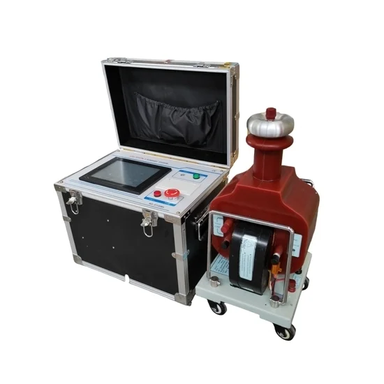
5 kVA 100 kV AC DC automatic hipot tester can directly measure the AC leakage current on the high voltage side, the range is 0-50ma, if you want to measure the DC high voltage side (0-140kV) leakage current, you need to add an additional DC milliampere meter, the range is 0-1.999ma.
Control Module Specifications
- Model: ATO-HTGTB-5100A
- Power Supply: AC 220V±10%, 50/60Hz
- Rated Power: 5kVA
- Output Voltage: 0~250V
- Input Current: 0~22.7A
- Time Range: 0-9999S
- Voltage Resolution: 0.1kV
- Current Resolution: 0.1mA
- Measurement Accuracy: ≤2%
- Ambient Temperature: 0~40℃
- Ambient Humidity: RH≤85%
- Gross Weight: 29kgs
- Package Dimension: 500*370*450mm
Test Transformer (HV Unit) Specifications
- Output Voltage Waveform: Sine Wave
- Output Waveform Distortion Rate: ≤1%.
- No-Load Loss: 0.2%~0.35%
- Induced Voltage Level: 1.1Uo/1min.
- Surface Temperature Rise: <55℃
- Rated Capacity: 5kVA
- Rated Input Voltage: 0~200V
- Rated Input Current: 25A
- Testing Voltage: AC 100kV
- Rated Output Current: 50mA
- Output DC High Voltage: 140kV
- Hipot Time: 1min
- Gross Weight: 94kgs
- Package Dimension: 500*430*1230mm
- Permissible Continuous Operating Time at Rated Capacity: 0.5 hours (Long-Running Transformers Can be Ordered)
- Consecutive Running Times: Below 10kVA, Each Interval of 2 Hours, Allows Continuous Operation of 0.5 hours; Above 15kVA, Every 4 hours, Allowing Continuous Operation for 0.5 hours; Allows Continuous Operation for 4 hours at Half Rated Voltage And Half Rated Current.
Panel Descriptions
- There are miniature thermal printers in AC and DC high voltage test equipment. Press the print button on the panel to print out the results.
- The contrast of the LCD display can be adjusted.
- Turn on the indicator light, which will light up when the test starts.
- Zero indicator light. When the voltage regulator is at the zero position, this lamp will light.
- Alarm indicator. When a fault or protective action occurs, the light is on.
- LCD screen, 320X240 dot matrix, white backlight.
- Wiring diagram, refer to the wiring diagram for AC and DC testing.
- Keyboard, interactive terminal between user and device.
- Buzzer, sound alarm.
- Emergency stop button, press this button to cut off the power and end.
AC Test Wiring Diagram
DC Test Wiring Diagram
Note:
CM: Control box
TT: Test transformer
WR:Water resistance
TO: Test object
GM: Diode
Reviews
There are no reviews yet.