
Description
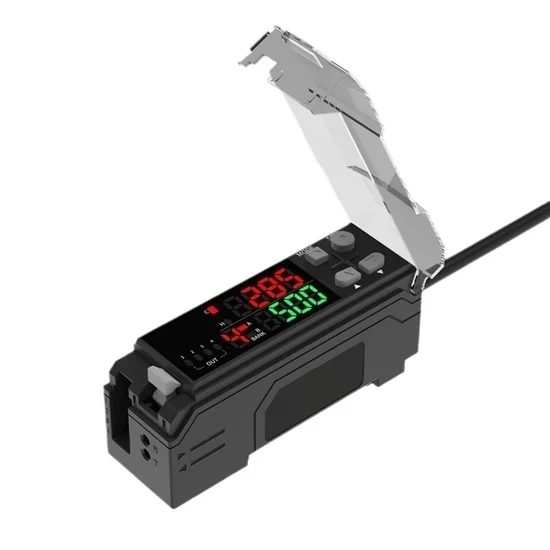
RGB fiber optic color sensor is equipped with a dedicated fiber optic sensor head, featuring micro-color difference recognition function. It supports triple 16-bit calculation for precise RGB target recognition, enabling accurate identification of over 3,000 colors. With an 8-channel design, ATO color sensor can store 8 colors at a time and detect 4 colors simultaneously. It also has three detection modes: C, CI, and SUPER I, making it suitable for various application scenarios. Digital color sensor is a high-quality color detection device with small size, high power, high recognition accuracy, and wide applicability.
Specification
Fiber Optical Color Sensor
| Model | ATO-FW-V21N | ATO-FW-V21P |
| Transistor Type | NPN | PNP |
| Weight (with 2m Cable) | 150g | |
| Shell/Cover Material | PC | |
| Length of Optical Fiber Cable | 1m | |
| Outer Diameter of Optical Fiber | M6 | |
| Inner Diameter of Optical Fiber Inner | Φ1*1 | |
| Output Signal | Switch Quantity | |
| External Calibration Input Time | 20ms (minimum value) | |
| Power Supply | 24VDC, Ripple (P-P): Max 10% | |
| Environment Temperature | -10~+55℃, No Condensation | |
| Current Consumption | Normal Mode: 1.5W (Max 62.5mA) Eco Mode: 1W (Max 42.0mA) |
|
| Timer Function | Adjustable from 1 to 1,000ms (for each area separately) | |
| Response Time | 200μS(HSP) /1ms(FINE) /4ms(TURBO) /8ms(SUPER) | |
| Light Source | Red LED 665nm/Green LED 520nm/Blue LED 465nm | |
| Control Output | NPN(PNP) Open Collector X4 Channels, Max 40VDC 1 Output up to 100mA, Total 4 Outputs up to 200mA Residual Voltage Max 1V |
|
| Vibration Resistance | 10 to 55Hz, 1.5mm Double Amplitude, in X, Y, Z Directions, 2 Hours Each | |
| Protection Circuit | Reverse Polarity Protection/Overcurrent Protection/Overvoltage Protection |
Sensor Head
| Model | ATO-FW-H35 | ATO-FW-H37 |
| Detection Range | 28-52mm | 11-20mm |
| Minimum Fiber Bending Radius | 25mm | 15mm |
| Weight (with 2m Cable) | 40g | 45g |
| Lens Cover Material | Polyarylate | PC, 304 Stainless Steel |
| Type | Large Spot Long Distance | Gloss Elimination, Small Beam Spot |
| Minimum Spot Diameter | 4.5mm Diameter at 40mm Reference Distance | 1mm Diameter at 16mm Reference Distance |
| Housing Material | PC | |
| Protection Class | IP40 | |
| Environment Temperature | -10 to +55℃, No Condensation | |
| Environment Illuminance | Incandescent: Max 10,000lux Daylight: Max 20,000lux |
|
| Vibration Resistance | 10 to 55Hz, 1.5mm Double Amplitude, in X, Y, Z Directions, 2 Hours Each |
Note: ATO-FW-V21N is sold together with ATO-FW-H35, and ATO-FW-V21P is sold together with ATO-FW-H37.
Features
- Color recognition capability: Equipped with a dedicated color probe, it can accurately identify more than 3,000 kinds of colors; fiber optic color sensor has a micro-color difference recognition function, supports triple 16-bit computing RGB for precise target recognition, and color signals are converted into 16-bit data in the receiver.
- Channels and storage: Adopting an 8-channel design, it can store 8 colors at one time and detect 4 colors simultaneously.
- Color sensor performance: Using a small-sized, high-power dedicated detection head with a composite structure. The transmitter uses optic fiber to generate a single light spot, reducing the volume of the sensor head and improving detection capability and stability. ATO color sensor has three built-in detection modes, suitable for various application scenarios.
Dimension (Unit=mm)
Detail
Wiring Method
External Input Settings
Set Sensitivity via External Input (External Tuning)
- Activate the key lock function.
- Connect the pink wire to an external device, such as a switch or PLC.
- Short-circuit the pink wire as shown in the diagram; for each model, this is equivalent to pressing the SET (setting) button.
Select Database via External Input (In C/C+I Mode)
- Activate the key lock function.
- Connect the purple wire to an external device, such as a switch or PLC.
- Short-circuit the purple wire as shown in the diagram, so that each model switches the database from A to B. (When the input signal is ON, the database is set to B.)
External Input Shift Input (During Super I Mode Setting)
- Connect the purple wire to an external device, such as a switch or PLC.
- Short-circuit the purple wire as shown in the diagram to enable shift input for each model. (The rising edge of the input signal executes the shift input.)
Tips: How to Select Correct Mode for Fiber Optic Color Sensor?
When using fiber optical color sensor, selecting the correct detection mode is crucial for ensuring accurate detection. The sensor has three built-in modes: C, CI, and SUPER I, each with its own characteristics, and the selection needs to be based on the detection requirements.
- C mode: If it is necessary to deal with scenarios where workpieces are moving or vibrating, and there is no need to distinguish neutral colors such as white, black, or gray, the C mode (RGB comparison) is a suitable choice, as it performs well in such scenarios.
- CI mode: When there is a need to detect subtle differences in colors, with low requirements for distinguishing neutral colors and acceptable influence from workpiece vibration, the CI mode (RGB comparison+light-dark comparison, receiving light brightness) can meet the needs and accurately capture tiny differences between colors.
- SUPER I mode: If there is a need to distinguish neutral colors (black and white) and the influence from workpiece vibration is acceptable, the SUPER I mode (light-dark comparison, receiving light brightness) is more applicable, as it can effectively identify neutral colors.
In summary, the correct detection mode for the color sensor can be selected based on the requirements for distinguishing neutral colors, and whether the workpiece has vibration and movement.
Reviews
There are no reviews yet.